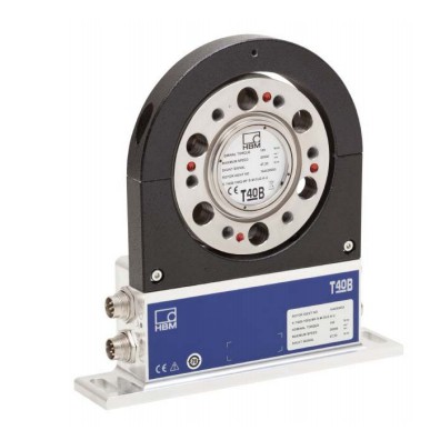
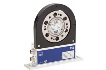
T40B 以高精度、再现性和鲁棒性而著称,非常适合用于静态和动态扭矩测量。包括滞后和高温稳定性,扭矩传感器具有 0.03% 的线性精度。可内置磁学转速测量系统,在传动系统中进行功率测量。非接触设计和数字信号传输确保了更高的安全性,并具有免维护特性。EtherCAT 的 TIM-EC接口模块和 PROFINET 的 TIM-PN 可将扭矩和转速信号与最先进的测试台系统进行集成,确保获得最高的性能和高灵活性。
HBM 精度等级: 0.05
额定扭矩: 50 Nm 到 10 kNm
产品名称:T40B扭矩传感器、T40B转矩传感器,T40B扭力传感器
产品品牌:德国HBM扭矩传感器,HBM转矩传感器,HBM扭力传感器
T40B扭矩传感器产品特点:
高精度
线性度(包括滞后)仅为0.03%
高温稳定性
比例计量法确保更高的测量精度和稳定性
极具成本效益的高性能扭矩传感器,用于测试台,测量结果具有极高的精度和再现性
可靠
带错误检测的数字传输确保了无干扰数据传输
强度高,坚固耐用
创新数字数据传输提供可靠的测量数据,即使在恶劣的环境条件下
灵活
坚固的磁学转速测量系统
模拟和数字接口,便于与不同测试台系统集成
可选带有参考脉冲的鲁棒磁学转速测量系统,用于获取绝对转子位置
极高灵活性,面向现在和未来的测量任务
产品参数规格
| Type |
T40B |
| Accuracy class |
0.1 |
0.05 |
| Torque measuring system |
| Nominal (rated) torque Mnom |
N⋅m |
50 |
100 |
200 |
500 |
|
| kN⋅m |
|
|
|
|
1 |
2 |
|
5 |
10 |
Nominal (rated) rotational speed
standard speed (option M) high speed (option H) |
U/min U/min |
20000 |
15000
18000 |
12000
14000 |
10000
12000 |
| 24000 |
23000 |
Non-linearity including hysteresis,
related to the nominal (rated) sensitivity Frequency output
For a max. torque in the range:
between 0% of Mnom and 20% of Mnom
> 20% of Mnom and 60% of Mnom
> 60% of Mnom and 100% of Mnom
Voltage output
For a max. torque in the range:
between 0% of Mnom and 20% of Mnom
> 20% of Mnom and 60% of Mnom
> 60% of Mnom and 100% of Mnom
Relative standard deviation of the repeatability,
per DIN 1319, related to the variation of the output signal Frequency output
Voltage output |
%
%
%
%
%
%
%
% |
<土0.01
<土0.02
<土0.03
<土0.01
<土0.02
<土0.03
<土 0.03
<土 0.03 |
Temperature effect per 10 K in the nominal (rated) temperature range
on the output signal, related to the actual value of the signal span
Frequency output Voltage output
on the zero signal, related to the nominal (rated) sensitivity
Frequency output Voltage output |
%
%
%
% |
土0.1 土0.05
土0.4 土0.2 |
土0.1
土0.2 |
土0.05
土0.1 |
Nominal (rated) sensitivity (span between torque = zero and nominal (rated) torque)
Frequency output 10 kHz / 60 kHz / 240 kHz Voltage output
Sensitivity tolerance (deviation of the actual output quantity at Mnom from the nominal (rated) sensitivity) Frequency output
Voltage output |
kHz V
%
% |
5/30/120
10
土0.1 土0.1 |
Output signal at torque = zero
Frequency output Voltage output |
kHz V |
10/60/240
0 |
Nominal (rated) output signal
Frequency output
with positive nominal (rated) torque with negative nominal (rated) torque Voltage output
with positive nominal (rated) torque with negative nominal (rated) torque |
kHz kHz
V V |
15 1) / 90 2) / 360 3) (5 V symmetrical 4))
5 1) / 30 2) / 120 3) (5 V symmetrical 4))
+10
−10 |
Load resistance Frequency output Voltage output
Long-term drift over 48 h at reference temperature
Frequency output Voltage output |
kΩ kΩ
%
% |
≥ 2
≥ 10 |
<土0.06
<土0.06 |
<土0.03
<土0.03 |
| Measurement frequency range, −3 dB |
kHz |
1 1) / 3 2) / 6 3) |
| Group delay |
μs |
<400 1) / <220 2) / <150 3) |
Residual ripple
Voltage output 5) |
mV |
<40 |
| Specifications (continued) |
|
|
|
|
|
|
|
|
|
|
|
|
|
|
|
|
|
|
|
|
|
|
|
|
| Nominal (rated) torque Mnom |
N⋅m |
50 |
# |
200 |
500 |
|
| kN⋅m |
|
|
|
|
1 |
2 |
3 |
5 |
10 |
Maximum modulation range 6)
Frequency output Voltage output |
kHz V |
2.5 to 17.5 1) / 15 to 105 2) / 60 to 420 3)
−12 to +12 |
Energy supply
Nominal (rated) supply voltage (separated extra-low DC voltage)
Current consumption in measuring mode Current consumption in startup mode Nominal (rated) power consumption Maximum cable length |
V A A W
m |
18 to 30
< 1
< 4 (typ. 2) 50 μs
< 10
50 |
Shunt signal
Tolerance of the shunt signal, related to Mnom
Nominal (rated) trigger voltage Trigger voltage limit
Shunt signal ON Shunt signal OFF |
% V V V V |
approx. 50% of Mnom
<土 0.05
5
36
min. >2.5
max. <0.7 |
| Rotational speed measuring system |
| Measurement system |
|
Magnetic, via AMR sensor (Anisotropic Resistive Effect) and magnetized plastic ring with embedded steel ring |
| Magnetic poles |
|
72 |
86 |
108 |
126 |
156 |
| Maximum positional variation of the poles |
|
50 angular seconds |
| Output signal |
V |
5 V symmetrical (RS−422);
2 square wave signals approx. 90° phase shifted |
| Pulses per revolution |
|
1024 (Option 6, Code 1 & A)
128 (Option 6, Code 2 & B) |
| Min. rotational speed for sufficient pulse stability |
rpm |
0 |
| Pulse tolerance 7) |
degrees |
<土0.05 |
| Maximum permissible output frequency |
kHz |
420 |
| Group delay |
μs |
<150 |
| Radial nominal (rated) distance between sensor head and magnetic ring (mechanical distance) |
mm |
1.6 |
| Working distance range between sensor head and magnetic ring |
mm |
0.4 to 2.5 |
| Max. permissible axial displacement of the rotor to the stator 8) |
mm |
土1.5 |
Hysteresis of direction of rotation reversal in the case of relative vibrations betw. rotor and stator
Torsional vibration of the rotor Horizontal stator vibration displacement |
degrees mm |
<approx. 0.2
<approx. 0.5 |
| Magnetic load limit Remanent flux density Coercive field strength |
mT kA/m |
>100
>100 |
| Permissible magnetic field strength for signal deviations |
kA/m |
<0.1 |
| Load resistance 9) |
kΩ |
≥2 |
| Reference signal measuring system (0 index) |
| Measurement system |
|
Magnetic, with Hall sensor and magnet |
| Output signal |
V |
5 V symmetrical (RS-422) |
| Pulses per revolution |
|
1 |
| Min. rotational speed for sufficient pulse stability |
rpm |
2 |
| Pulse width, approx. |
degrees |
0.088 |
| Pulse tolerance 7) |
degrees |
<土0.05 |
| Group delay |
μs |
<150 |
| Axial nominal (rated) distance between sensor head and magnetic ring (mechanical distance) |
mm |
2.0 |
| Max. permissible axial displacement of rotor to stator 8) |
mm |
土1.5 |
| Nominal (rated) torque Mnom |
N⋅m |
50 |
# |
200 |
500 |
|
| kN⋅m |
|
|
|
|
1 |
2 |
3 |
5 |
10 |
| General information |
| EMC |
|
|
Emission (per FCC 47, Part 15, subpart C) 10)
Emission (per EN 61326−1, Section 7) RFI field strength) 11) |
−
− |
Class B |
Immunity from interference (EN 61326−1, Table 2) Electromagnetic field (AM)
Magnetic field
Electrostatic discharge (ESD)
Contact discharge Air discharge
Fast transients (burst) Impulse voltages (surge) Conducted interference (AM) |
V/m A/m
kV kV kV kV V |
10
100
4
8
1
1
10 |
| Degree of protection per EN 60 529 |
|
IP 54 |
Reference temperature
Nominal (rated) temperature range Operating temperature range 12) Storage temperature range |
°C
°C
°C
°C |
23
+10 to +70
−20 to +85
−40 to +85 |
Mechanical shock per EN 60068−2−27 13)
Number Duration
Acceleration (half sine) |
n ms m/s2 |
1000
3
650 |
Vibrational stress in 3 directions per EN 60068−2−6 13)
Frequency range Duration
Acceleration (amplitude) |
Hz h
m/s2 |
10 to 2000
2.5
200 |
Load limits 14)
Limit torque, related to Mnom 15) Breaking torque, related to Mnom15) Longitudinal limit force 16)
Lateral limit force 16)
Limit bending moment 16)
Oscillation width per DIN 50100 (peak-to-peak) 17) |
%
%
kN kN N⋅m N⋅m |
|
400
800
5
1
50
200 |
200
> 400 |
160
> 320 |
5
1
50
200 |
10
2
100
400 |
13
4
200
1000 |
19
5
220
2000 |
30
9
560
4000 |
35
10
600
4800 |
60
12
800
8000 |
80
18
1200
16000 |
| Specifications (continued) |
|
|
|
|
|
|
|
|
|
|
|
|
|
|
|
|
|
|
|
|
|
|
|
|
| Nominal (rated) torque Mnom |
N⋅m |
50 |
100 |
200 |
500 |
|
| kN⋅m |
|
|
|
|
1 |
2 |
3 |
5 |
10 |
| Mechanical values |
| Torsional stiffness cT Torsion angle at Mnom |
kN⋅m/rad degrees |
180
0.016 |
180
0.032 |
360
0.032 |
745
0.038 |
1165
0.049 |
2515
0.046 |
3210
0.054 |
5565
0.051 |
14335
0.040 |
Stiffness in the axial direction ca Stiffness in the radial direction cr
Stiffness during the bending moment round a radial axis cb |
kN/mm kN/mm
kN⋅m/deg. |
285
160
1.9 |
285
160
1.9 |
540
315
3.6 |
450
560
4.2 |
580
860
5.9 |
540
1365
9 |
570
1680
9.3 |
760
2080
20.2 |
960
2940
45.5 |
| Maximum deflection at longitudinal limit force |
mm |
< 0.04 |
< 0.05 |
< 0.06 |
< 0.08 |
< 0.09 |
| Additional max. radial deviation at lateral limit force |
mm |
< 0.02 |
| Additional plumb/parallel deviation at limit bending moment (at 0 dB) |
mm |
< 0.06 |
< 0.11 |
< 0.09 |
< 0.18 |
< 0.19 |
< 0.14 |
< 0.12 |
| Balance quality level per DIN ISO 1940 |
|
G 2.5 |
Max. limits for relative shaft vibration (peak-to-peak)18)
Undulations in the connection flange area, based on ISO 7919−3
Normal operation (continuous operation)
Start and stop operation/resonance ranges (temporary) |
μm μm |
s = 9000
(p-p) (n in rpm)
n
s = 13200
(p-p) (n in rpm)
n |
Mass moment of inertia of rotor Jv without rotational speed measuring system
with magn. rotational speed meas. system |
kg⋅m2 kg⋅m2 |
|
0.0010
0.0015 |
0.0010
0.0015 |
0.0017
0.0022 |
0.0039
0.0048 |
0.0128 |
0.0292
0.0333 |
0.0771
0.0872 |
| 0.0145 |
#### |
Proportional mass moment of inertia for the transmitter side (side of the flange with external centering)
without rotational speed measuring system
with magn. rotational speed meas. system |
% of Jv
% of Jv |
68
44 |
68
44 |
62
48 |
59
48 |
54
48 |
53
47 |
54
48 |
Max. permissible static eccentricity
of the rotor (radially) to the center point of the stator
without rotational speed measuring system |
mm |
土2 |
Permissible axial displacement between rotor and stator 19)
without rotational speed measuring system |
mm |
土2 |
Weight
Rotor without rotational speed measuring system
Rotor with magn. rotational speed meas. system
Stator |
kg kg kg |
0.7
0.8
1.1 |
0.7
0.8
1.1 |
1.1
1.3
1.1 |
1.9
2.1
1.1 |
3.8
4.1
1.1 |
3.9
4.1
1.1 |
6.5
6.9
1.2 |
10.9
11.7
1.3 |
| 类型 |
T40B |
| 准确度等级 |
0.1 |
0.05 |
| 扭矩测量系统 |
| 标称(额定)扭矩Mnom |
N⋅m |
50 |
100 |
200 |
500 |
|
| kN⋅m |
|
|
|
|
1 |
2 |
|
五 |
10 |
标称(额定)转速
标准速度(选项M)高速(选项H) |
U / min U / min |
20000 |
15000
18000 |
12000
14000 |
10000
12000 |
| 24000 |
23000 |
包括滞后的非线性,
与标称(额定)灵敏度相关的频率输出
最大值。扭矩范围:
0%的Mnom和20%的Mnom
> 20%的Mnom和60%的Mnom
> 60%的Mnom和100%的Mnom
电压输出
。扭矩范围:
0%Mnom和20%Mnom
> 20%Mnom和60%Mnom
> 60%Mnom和100%Mnom
重复性的相对标准偏差,
根据DIN 1319,与变化有关输出信号频率输出
电压输出 |
%
%
%
%
%
%
%
% |
<土0.01
<土0.02
<土0.03
<土0.01
<土0.02
<土0.03
<土0.03
<土0.03 |
输出信号额定(额定)温度范围内每10 K的温度效应,与信号量程的实际值有关
频率输出
零信号上的电压输出,与标称(额定)灵敏度有关
频率输出电压输出 |
%
%
%
% |
土0.1土0.05
土0.4土0.2 |
土0.1
土0.2 |
土0.05
土0.1 |
标称(额定)灵敏度(扭矩=零和额定(额定)扭矩之间的跨度)
频率输出10 kHz / 60 kHz / 240 kHz电压输出
灵敏度公差(Mnom处的实际输出量与标称(额定)灵敏度的偏差)频率输出
电压输出 |
千赫V
%
% |
5/30/120
10
土0.1土0.1 |
扭矩输出信号=零
频率输出电压输出 |
kHz V |
10/60/240
0 |
标称(额定)输出信号 带正向额定(额定)转矩的带有标称(额定)负转矩的
频率输出
带正负额定(额定)转矩的电压输出
带负额定(额定)转矩 |
kHz kHz
VV |
15 1)/ 90 2)/ 360 3)(5 V对称4))
5 1)/ 30 2)/ 120 3)(5 V对称4))
+10
-10 |
负载电阻频率输出电压输出
参考温度下48小时的长期漂移
频率输出电压输出 |
千欧千欧
%
% |
≥2
≥10 |
<土0.06
<土0.06 |
<土0.03
<土0.03 |
| 测量频率范围,-3 dB |
千赫 |
1 1)/ 3 2)/ 6 3) |
| 集团延迟 |
微秒 |
<400 1)/ <220 2)/ <150 3) |
剩余纹波
电压输出5) |
毫伏 |
<40 |
| 规格(续) |
|
|
|
|
|
|
|
|
|
|
|
|
|
|
|
|
|
|
|
|
|
|
|
|
| 标称(额定)扭矩Mnom |
N⋅m |
50 |
# |
200 |
500 |
|
| kN⋅m |
|
|
|
|
1 |
2 |
3 |
五 |
10 |
最大调制范围6)
频率输出电压输出 |
kHz V |
2.5至17.5 1)/ 15至105 2)/ 60至420 3)
-12至+12 |
能量供应
标称(额定)电源电压(分离的超低直流电压)
测量模式下的电流消耗启动模式下的电流消耗额定(额定)功耗最大电缆长度 |
VAAW
m |
18至30
<1
<4(典型值2)50μs
<10
50 |
分流信号分流信号的
容差,与Mnom
标称(额定)触发电压有关触发电压限制
分流信号ON分流信号OFF |
%VVVV |
约。50%Mnom
<土0.05
5
36
分钟。>
最多2.5 <0.7 |
| 转速测量系统 |
| 测量系统 |
|
磁性,通过AMR传感器(各向异性电阻效应)和带嵌入式钢环的磁化塑料环 |
| 磁极 |
|
72 |
86 |
108 |
126 |
156 |
| 极的最大位置变化 |
|
50角秒 |
| 输出信号 |
V |
5 V对称(RS-422);
2个方波信号约。90°相移 |
| 每转脉冲 |
|
1024(选项6,代码1和A)
128(选项6,代码2和B) |
| 闵。转速足以保证脉冲稳定性 |
转 |
0 |
| 脉冲容差7) |
度 |
<土0.05 |
| 最大允许输出频率 |
千赫 |
420 |
| 集团延迟 |
微秒 |
<150 |
| 传感器头与磁环之间的径向标称(额定)距离(机械距离) |
毫米 |
1.6 |
| 传感器头和磁环之间的工作距离范围 |
毫米 |
0.4到2.5 |
| 最大。允许轴向位移的转子到定子8) |
毫米 |
土1.5 |
在相对振动的情况下,旋转方向的滞后反转。转子和定子转子的
扭转振动水平定子的振动位移 |
度mm |
<约 0.2
<约 0.5 |
| 磁负载限制剩余磁通密度矫顽场强 |
mT kA / m |
> 100
> 100 |
| 信号偏差允许的磁场强度 |
千安/米 |
<0.1 |
| 负载电阻9) |
千欧 |
≥2 |
| 参考信号测量系统(0指标) |
| 测量系统 |
|
磁性,带霍尔传感器和磁铁 |
| 输出信号 |
V |
5 V对称(RS-422) |
| 每转脉冲 |
|
1 |
| 闵。转速足以保证脉冲稳定性 |
转 |
2 |
| 脉冲宽度,大约 |
度 |
0.088 |
| 脉冲容差7) |
度 |
<土0.05 |
| 集团延迟 |
微秒 |
<150 |
| 传感器头与磁环之间的轴向标称(额定)距离(机械距离) |
毫米 |
2.0 |
| 最大。转子到定子的允许轴向位移8) |
毫米 |
土1.5 |
| 标称(额定)扭矩Mnom |
N⋅m |
50 |
# |
200 |
500 |
|
| kN⋅m |
|
|
|
|
1 |
2 |
3 |
五 |
10 |
| 一般信息 |
| EMC |
|
|
排放(根据FCC 47,第15部分,子部分C)10)
排放(根据EN 61326-1,第7节)RFI场强)11) |
-
- |
B级 |
抗干扰性(EN 61326-1,表2)电磁场(AM)
磁场
静电放电(ESD)
接触放电空气放电
快速瞬变(脉冲串)脉冲电压(浪涌)传导干扰(AM) |
V / m A / m
kV kV kV kV kV |
10
100
4
8
1
1
10 |
| 符合EN 60 529的防护等级 |
|
IP 54 |
参考温度
标称(额定)温度范围工作温度范围12)存储温度范围 |
°C
°C
°C
°C |
23
+10到+70
-20到+85
-40到+85 |
EN 60068-2-27的机械冲击13)
数字持续时间
加速度(半正弦) |
n ms m / s2 |
1000
3
650 |
符合EN 60068-2-6标准的3个方向的振动应力13)
频率范围持续时间
加速度(振幅) |
赫兹h
m / s2 |
10至2000
2.5
200 |
负载极限14)
与Mnom相关的极限扭矩15)与Mnom相关的断裂扭矩15)纵向极限力16)
侧向极限力16)
极限弯矩16)
根据DIN 50100(峰峰值)振荡宽度17) |
%
%
千牛千牛N⋅mN⋅m |
|
400
800
5
1
50
200 |
200
> 400 |
160
> 320 |
5
1
50
200 |
10
2
100
400 |
13
4
200
1000 |
19
5
220
2000 |
30
9
560
4000 |
35
10
600
4800 |
60
12
800
8000 |
80
18
1200
16000 |
| 规格(续) |
|
|
|
|
|
|
|
|
|
|
|
|
|
|
|
|
|
|
|
|
|
|
|
|
| 标称(额定)扭矩Mnom |
N⋅m |
50 |
100 |
200 |
500 |
|
| kN⋅m |
|
|
|
|
1 |
2 |
3 |
五 |
10 |
| 机械价值 |
| 扭转刚度cT在Mnom处的扭转角 |
kN·m / rad度 |
180
0.016 |
180
0.032 |
360
0.032 |
745
0.038 |
1165
0.049 |
2515
0.046 |
3210
0.054 |
5565
0.051 |
14335
0.040 |
轴向的刚度c径向的
刚度cr 弯曲力矩的径向轴cb的刚度 |
kN / mm kN / mm kN·
m / deg。 |
285
160
1.9 |
285
160
1.9 |
540
315
3.6 |
450
560
4.2 |
580
860
5.9 |
540
1365
9 |
570
1680
9.3 |
760
2080
20.2 |
960
2940
45.5 |
| 纵向极限力下的最大挠度 |
毫米 |
<0.04 |
<0.05 |
<0.06 |
<0.08 |
<0.09 |
| 额外的最大 侧向力的径向偏差 |
毫米 |
<0.02 |
| 极限弯矩下的额外铅锤/平行偏差(0 dB) |
毫米 |
<0.06 |
<0.11 |
<0.09 |
<0.18 |
<0.19 |
<0.14 |
<0.12 |
| 根据DIN ISO 1940平衡质量等级 |
|
G 2.5 |
最大。相对轴振动的限制(峰 - 峰值)18)
连接法兰区域的波动,基于ISO 7919-3
正常运行(连续运行)
启动和停止运行/共振范围(临时) |
μmμm |
s = 9000
(pp)(n以rpm计)
n
s = 13200
(pp)(n,以rpm为单位)
n |
没有转速测量系统的转子Jv的质量惯性矩
。转速测量 系统 |
kg⋅m2kg⋅m2 |
|
0.0010
0.0015 |
0.0010
0.0015 |
0.0017
0.0022 |
0.0039
0.0048 |
0.0128 |
0.0292
0.0333 |
0.0771
0.0872 |
| 0.0145 |
#### |
变速器侧(带外部定心的法兰侧)的比例质量惯性矩,无转速测量系统
。转速测量 系统 |
Jv
%的Jv% |
68
44 |
68
44 |
62
48 |
59
48 |
54
48 |
53
47 |
54
48 |
最大。
在
没有转速测量系统的情况下,转子(径向)到定子中心点的允许静态偏心率 |
毫米 |
土2 |
转子和定子之间的允许轴向位移19)
没有转速测量系统 |
毫米 |
土2 |
无转速测量系统的重量转子带转速的
转子。转速测量 系统
定子 |
kg kg kg |
0.7
0.8
1.1 |
0.7
0.8
1.1 |
1.1
1.3
1.1 |
1.9
2.1
1.1 |
3.8
4.1
1.1 |
3.9
4.1
1.1 |
6.5
6.9
1.2 |
10.9
11.7
1.3 |
Radial and axial run-out tolerances(径向和轴向跳动公差)

| Measuring range (N·m) |
Axial runout tolerance (mm) |
Radial run-out tolerance (mm) |
| 50 |
0.01 |
0.01 |
| 100 |
0.01 |
0.01 |
| 200 |
0.01 |
0.01 |
| 500 |
0.01 |
0.01 |
| 1 k |
0.01 |
0.01 |
| 2 k |
0.02 |
0.02 |
| 3 k |
0.02 |
0.02 |
| 5 k |
0.02 |
0.02 |
| 10 k |
0.02 |
0.02 |
Dimensions of T40B 50 Nm - 100�Nm without rotational speed measurement
Dimensions in mm (1 mm = 0.03937 inches)
Dimensions without tolerances, per DIN ISO 2768-mk

Dimensions of T40B 50 Nm - 100�Nm without rotational speed measurement, continued
Dimensions in mm (1 mm = 0.03937 inches)
Dimensions without tolerances, per DIN ISO 2768-mk

Dimensions of T40B 200�Nm without rotational speed measurement
Dimensions in mm (1 mm = 0.03937 inches)
Dimensions without tolerances, per DIN ISO 2768-mk

Dimensions of T40B 200�Nm without rotational speed measurement, continued
Dimensions in mm (1 mm = 0.03937 inches)
Dimensions without tolerances, per DIN ISO 2768-mk

Dimensions of T40B 500�Nm - 1�kNm without rotational speed measurement
Dimensions in mm (1 mm = 0.03937 inches)
Dimensions without tolerances, per DIN ISO 2768-mk

Dimensions of T40B 500�Nm - 1�kNm without rotational speed measurement, continued
Dimensions in mm (1 mm = 0.03937 inches)
Dimensions without tolerances, per DIN ISO 2768-mk

Dimensions of T40B 2�kNm - 3�kNm without rotational speed measurement
Dimensions in mm (1 mm = 0.03937 inches)
Dimensions without tolerances, per DIN ISO 2768-mk

Dimensions of T40B 2�kNm - 3�kNm without rotational speed measurement, continued
Dimensions in mm (1 mm = 0.03937 inches)
Dimensions without tolerances, per DIN ISO 2768-mk

Dimensions of T40B 5�kNm without rotational speed measurement
Dimensions in mm (1 mm = 0.03937 inches)
Dimensions without tolerances, per DIN ISO 2768-mk

Dimensions of T40B 5�kNm without rotational speed measurement, continued
Dimensions in mm (1 mm = 0.03937 inches)
Dimensions without tolerances, per DIN ISO 2768-mk

Dimensions of T40B 10�kNm without rotational speed measurement
Dimensions in mm (1 mm = 0.03937 inches)
Dimensions without tolerances, per DIN ISO 2768-mk

Dimensions of T40B 10�kNm without rotational speed measurement, continued
Dimensions in mm (1 mm = 0.03937 inches)
Dimensions without tolerances, per DIN ISO 2768-mk


 售前咨询
售前咨询