| Specifications for T21WN |
|
|
|
|
|
|
|
|
|
|
|
|
|
|
|
|
|
|
|
|
|
|
|
|
|
|
|
|
|
|
|
|
|
|
| Type |
T21WN |
| Accuracy class |
0.2 |
| Nominal (rated) torque Mnom |
N×m |
0.1 |
0.2 |
0.5 |
1 |
2 |
5 |
10 |
20 |
50 |
100 |
200 |
| Nominal (rated) rotational speed |
rpm |
20,000 |
19,000 |
13,500 |
Non-linearity including hysteresis relative to the
nominal (rated) sensitivity |
% |
<±0.1 |
Rel. standard deviation of repeatability per
DIN 1319 relative to the variation of the output signal |
% |
<土0.05 |
Temperature effect per 10 K in the nominal (rated) temperature range
on the output signal relative to the actual value of the signal span
Frequency output Voltage output
on the zero signal relative to the nominal (rated) sensitivity
Frequency output Voltage output |
%
%
%
% |
<±0.1
≤±0.1
<±0.2
<±0.2 |
Nominal (rated) sensitivity (nominal (rated)
signal range between torque = zero and nominal (rated) torque)
Frequency output 10 kHz Voltage output
Sensitivity tolerance (deviation of actual output
quantity at Mnom from the nominal (rated) signal range) |
kHz V
% |
5
10
±0.2 |
Nominal output signal
Frequency output (RS422, 5V symmetrical)
with positive nominal (rated) torque with negative nominal (rated) torque
Voltage output
with positive nominal (rated) torque with negative nominal (rated) torque
Load resistance
Longterm drift over 48 h Cut-off frequency (‐3 dB)
Residual ripple (voltage output) Group delay |
kHz kHz
V V MΩ
mV kHz mVSS
ms |
15
5
+10
‐10
> 1
<±50
1
< 100
< 1.0 |
Maximum modulation range
Frequency output Voltage output |
kHz V |
3.7 … 16.3
-11 … +11 |
Resolution
Frequency signal Voltage signal |
mHz mV |
0.19
0.38 |
Energy supply
Nominal (rated) supply voltage (safety extralow voltage (SELV))
Calibration signal triggering
Current consumption in measuring mode Nominal (rated) power consumption Permissible residual ripple of supply voltage |
V (DC) V
A W
mVss |
10 ¼ 28.8
5 ¼ 24
with Ub 12V <0.2
< 2.4
200 |
| Calibration signal |
V |
+10土0.2% |
| Output signal at torque = zero |
V
Hz |
0 ±0.05
0 ±50 |
| Nominal (rated) torque Mnom |
N×m |
0.1 |
0.2 |
0.5 |
1 |
2 |
5 |
10 |
20 |
50 |
100 |
200 |
| Measurement system for rotational speed/angle of rotation |
| Measurement system |
Number |
Optical |
| Pulses per revolution |
360 |
| Output signal |
V |
5 (unbalanced); two square wave signals phase shifted by approx. 90° |
| Minimum rotational speed for sufficient pulse |
|
|
| stability |
rpm |
0 |
| Load resistance |
kΩ |
>10 |
| Group delay |
ms |
<3 |
|
|
for 1.5 m cable between T21WN and VK20A junction box |
|
|
(without VK20A, the group delay is dependent on the connected impedance / |
|
|
cable & analysis device) |
| Max. measurable rotational speed |
rpm |
20,0001) |
| General information |
| EMC |
V/m |
10 |
| Immunity to interference (per EN61326-1, table |
| A.1) |
| Electromagnetic field |
| Magnetic field |
A/m |
30 |
| Electrostatic discharge (ESD) |
|
|
| Contact discharge |
kV |
4 |
| Air discharge |
kV |
4 |
| Fast transients (burst) |
kV |
2 |
| Impulse voltage (surge) |
kV |
1 |
| Conducted interference |
V |
10 |
Emission (per EN 61326-1, table 3)
RFI voltage RFI power
RFI field strength |
|
Class B Class B Class B |
| Degree of protection per EN 60 529 |
|
IP40 |
| Weight, approx. |
kg |
0.17 |
0.60 |
1.3 |
| Nominal (rated) temperature range |
°C |
+5 ¼ +45 |
| Operating temperature range |
°C |
0 ¼ +60 |
| Storage temperature range |
°C |
-5 ¼ +70 |
| Mechanical shock and impact testing per EN |
n |
1000 |
| 60068-2-27; IEC 68‐2‐27‐1987 |
| Number |
| Duration |
ms |
3 |
| Acceleration (half sine) |
m/s2 |
650 |
| Vibration testing per EN 60068-2-6: |
Hz |
5 ¼ 65 |
| IEC 68‐2‐6‐1982 |
| Frequency range |
| Duration |
h |
1.5 |
| Acceleration (amplitude) |
m/s2 |
50 |
| Load limits 1) |
% |
|
|
|
2003) |
|
|
|
|
|
| Torque limit relative to Mnom |
| Breaking torque relative to Mnom |
% |
|
|
|
> 280 |
|
|
|
|
|
| Longitudinal limit force |
kN |
0.2 |
|
0.34 |
0.5 1.1 |
1.75 |
2.75 |
5.3 |
7.6 |
12.5 |
| Lateral limit force |
N |
3.6 |
|
5.7 |
8.3 18.2 |
29 |
46 |
88 |
127 |
207 |
| Bending moment limit |
N×m |
0.12 |
|
0.23 |
0.4 0.93 |
1.9 |
3.7 |
10 |
17 |
36 |
| Oscillation bandwidth per DIN 50 100 (peak-to- |
|
|
|
|
|
|
|
|
|
|
| peak)4) |
% |
|
|
|
80 |
|
|
|
|
|
| Nominal (rated) torque Mnom |
N×m |
0.1 |
0.2 |
0.5 |
1 |
2 |
5 |
10 |
20 |
50 |
100 |
200 |
| Mechanical values |
| Torsional stiffness cT |
kN×m/ rad |
0.03 |
0.05 |
0.07 |
0.91 |
1.9 |
3.25 |
14 |
21.9 |
32.6 |
| Torsion angle at Mnom |
degrees |
0.2 |
0.38 |
0.96 |
1.1 |
1.7 |
0.32 |
0.3 |
0.35 |
0.2 |
0.26 |
0.35 |
| Max. limits for relative shaft vibration (peak-to- peak) 5) |
mm |
4500
smax = n |
Effective vibration rate in the enclosure area per
VDI 2056 |
mm/s |
n veff = 3 |
| Mass moment of inertia of the rotor (around rotary axis) with rotational speed measuring system (x10‐3) |
gm2 |
0.06 |
0.063 |
0.068 |
6.10 |
6.13 |
6.23 |
53.7 |
54.6 |
57.2 |
| Balance quality level per DIN ISO 1940 |
- |
G 6.3 |
| 1) Dependent on the nominal (rated) torque |
|
|
|
|
|
|
|
|
|
|
|
|
|
|
|
|
|
|
|
|
|
|
|
|
|
|
|
|
|
|
|
|
| 2) Each type of irregular stress (bending moment, lateral or longitudinal force, exceeding nominal (rated) torque) can only be permitted up to its specified static load limit and provided none of the others can occur at the same time. If this condition is not met, the limit values must be |
| reduced. If 30% of the bending limit moment and lateral limit force occur at the same time, only 40% of the axial limit force is permissible and the nominal (rated) torque must not be exceeded. The permissible bending moments, longitudinal forces and lateral forces can affect the measurement result by approx. 1 % of the nominal (rated) torque. |
| 3) Note the maximum torque (TKmax) of the coupling. |
|
|
|
|
|
|
|
|
|
|
|
|
|
|
|
|
|
|
|
|
|
|
|
|
|
|
|
|
|
| 4) The nominal (rated) torque must not be exceeded. |
|
|
|
|
|
|
|
|
|
|
|
|
|
|
|
|
|
|
|
|
|
|
|
|
|
|
|
|
|
| 5) Relative undulations, following DIN 45670/VDI 2059. |
|
|
|
|
|
|
|
|
|
|
|
|
|
|
|
|
|
|
|
|
|
|
|
|
|
|
|
|
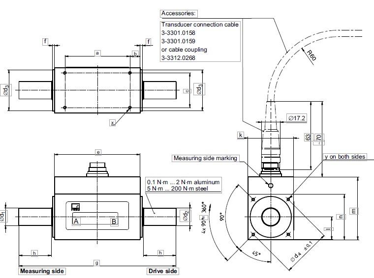
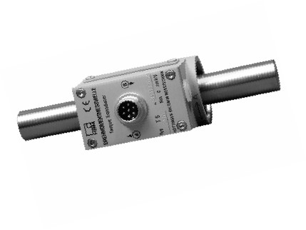
| Dimensions of T21WN |
|
|
|
|
|
|
|
|
|
|
|
|
|
|
|
|
|
|
|
|
|
|
|
|
|
|
|
|
|
|
|
|
|
|
|
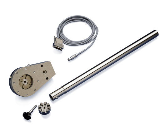
| Accessories: |
|
|
|
|
|
|
|
|
|
|
|
|
|
|
|
|
|
|
|
|
|
|
|
|
|
|
|
|
|
|
|
|
|
|
|
|
|
|
|
|
|
| Transducer connection cable 3-3301.0158 |
|
|
|
|
|
|
|
|
|
|
|
|
|
|
|
|
|
|
|
|
|
|
|
|
|
|
|
|
|
|
|
|
| f f 3-3301.0159 |
|
|
|
|
|
|
|
|
|
|
|
|
|
|
|
|
|
|
|
|
|
|
|
|
|
|
|
| a b or cable coupling 3-3312.0268 |
|
|
|
|
|
|
|
|
|
|
|
|
|
|
|
|
|
|
|
|
|
|
|
|
|
|
| Æ17.2 |
|
|
|
|
|
|
|
|
|
|
|
|
|
|
|
|
|
|
|
|
|
|
|
|
|
|
|
|
|
|
|
|
|
|
|
|
|
|
|
|
|
| k |
|
|
|
|
|
|
|
|
|
|
|
|
|
|
|
|
|
|
|
|
|
|
|
|
|
|
|
|
|
|
|
|
|
|
|
|
|
|
|
|
|
|
| Measuring side marking |
|
|
|
|
|
|
|
|
|
|
|
|
|
|
|
|
|
|
|
|
|
|
|
|
|
|
|
|
|
|
|
|
|
|
|
|
|
|
| y on both sides |
|
|
|
|
|
|
|
|
|
|
|
|
|
|
|
|
|
|
|
|
|
|
|
|
|
|
|
|
|
|
|
|
|
|
|
|
|
|
|
|
| 0.1 N×m ... 2 N×m aluminum |
|
|
|
|
|
|
|
|
|
|
|
|
|
|
|
|
|
|
|
|
|
|
|
|
|
|
|
|
|
|
|
|
|
|
|
|
|
| 5 N×m ... 200 N×m steel |
|
|
|
|
|
|
|
|
|
|
|
|
|
|
|
|
|
|
|
|
|
|
|
|
|
|
|
|
|
|
|
|
|
|
|
|
|
|
| A B |
|
|
|
|
|
|
|
|
|
|
|
|
|
|
|
|
|
|
|
|
|
|
|
|
|
|
|
|
|
|
|
|
|
|
|
|
|
|
|
|
|
| h |
|
|
|
|
|
|
|
|
|
|
|
|
|
|
|
|
|
|
|
|
|
|
|
|
|
|
|
|
|
|
|
|
|
|
|
|
|
|
|
|
|
|
| g |
|
|
|
|
|
|
|
|
|
|
|
|
|
|
|
|
|
|
|
|
|
|
|
|
|
|
|
|
|
|
|
|
|
|
|
|
|
|
|
|
|
|
| Measuring side |
|
|
|
|
|
|
|
|
|
|
|
|
|
|
|
|
|
|
|
|
|
|
|
|
|
|
|
|
|
|
|
|
|
|
|
|
|
|
|
|
| h |
|
|
|
|
|
|
|
|
|
|
|
|
|
|
|
|
|
|
|
|
|
|
|
|
|
|
|
|
|
|
|
|
|
|
|
|
|
|
|
|
|
|
| Drive side |
|
|
|
|
|
|
|
|
|
|
|
|
|
|
|
|
|
|
|
|
|
|
|
|
|
|
|
|
|
|
|
|
|
|
|
|
|
|
|
|
|
Measuring range
(N×m) |
Dimensions (in mm) |
| a |
b |
c |
e土1 |
f |
g |
h |
k土1 |
l |
m土1 |
n |
Æd1 g6 |
Æd2 g6 |
Æd 3 -0.1 |
Æd4 土0.1 |
y |
x |
| 0.1 |
40 |
11 |
22 |
62 |
2 |
95 |
14 |
28 |
14 |
54 |
30 |
6 |
8 |
27 |
32 |
M3/6 deep |
M3/5 deep |
| 0.2 |
40 |
11 |
22 |
62 |
2 |
95 |
14 |
28 |
14 |
54 |
30 |
6 |
8 |
27 |
32 |
M3/6 deep |
M3/5 deep |
| 0.5 |
40 |
11 |
22 |
62 |
2 |
95 |
14 |
28 |
14 |
54 |
30 |
6 |
8 |
27 |
32 |
M3/6 deep |
M3/5 deep |
| 1 |
40 |
11 |
22 |
62 |
2 |
95 |
14 |
28 |
14 |
54 |
30 |
6 |
8 |
27 |
32 |
M3/6 deep |
M3/5 deep |
| 2 |
40 |
11 |
22 |
62 |
2 |
95 |
14 |
28 |
14 |
54 |
30 |
6 |
8 |
27 |
32 |
M3/6 deep |
M3/5 deep |
| 5 |
60 |
9.5 |
32 |
79 |
2 |
145 |
30 |
42 |
21 |
58 |
42 |
16 |
16 |
38 |
46 |
M3/6 deep |
M3/6 deep |
| 10 |
60 |
9.5 |
32 |
79 |
2 |
145 |
30 |
42 |
21 |
58 |
42 |
16 |
16 |
38 |
46 |
M3/6 deep |
M3/6 deep |
| 20 |
60 |
9.5 |
32 |
79 |
2 |
145 |
30 |
42 |
21 |
58 |
42 |
16 |
16 |
38 |
46 |
M3/6 deep |
M3/6 deep |
| 50 |
42 |
15 |
40 |
72 |
3 |
170 |
45 |
56 |
28 |
73 |
56 |
26 |
26 |
54 |
65 |
M4/8 deep |
M4/8 deep |
| 100 |
42 |
15 |
40 |
72 |
3 |
170 |
45 |
56 |
28 |
73 |
56 |
26 |
26 |
54 |
65 |
M4/8 deep |
M4/8 deep |
| 200 |
42 |
15 |
40 |
72 |
3 |
170 |
45 |
56 |
28 |
73 |
56 |
26 |
26 |
54 |
65 |
M4/8 deep |
M4/8 deep |


 售前咨询
售前咨询