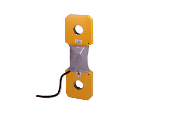
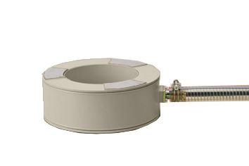
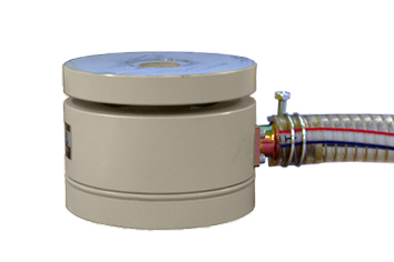
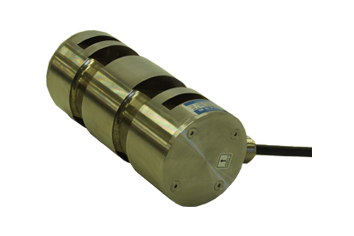
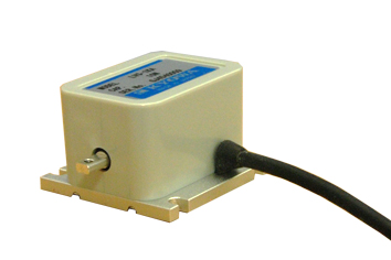
日本kyowa 六分力传感器 LFM-A 6分力传感器可同时测量直交3轴方向的动作力(Fx,Fy,Fz)与各轴周围的力矩(Mx,My,Mz),并可输出8成分的应变量。通过使用8个通道的应变测量器进行测量后,并按照附件中的干扰补正系数相乘、相加后,可计算出6成分的物理量。(标配简易输出值转换Excel®文件)如为可将测量值输出到Excel®的应变测量器,则在选定时无特别限制。还可通过使用动态数据收录软件(DCS-100A)与四则演算(DCS-101A),设定计算公式※1 进行实时矩阵演算(干扰补正)。适用于各种不同试验条件的设定,以及进行比较等时较为简易的实验用途。
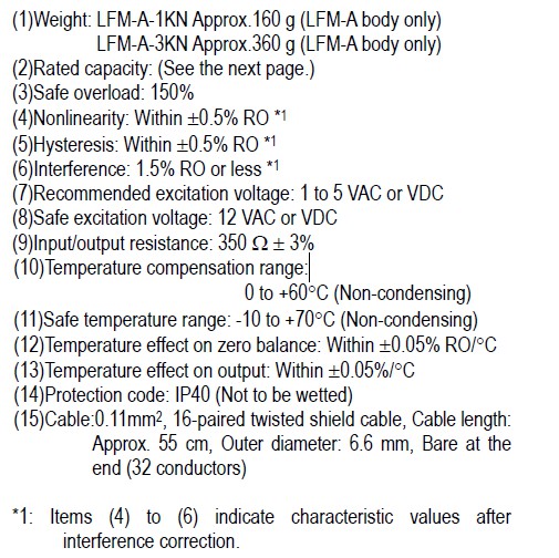
规格技术参数:
| 性能 |
额定容量 |
参照表 |
| 非线性 |
±0.5%RO或以内 |
| 滞后 |
±0.5%RO或以内 |
| 干扰度 |
±1.5%RO(按照附件的干扰补正系数补正后 |
| 额定输出 |
参照表 |
| 环境特性 |
允许使用温度范围 -10℃~70℃(无结露现象) |
| 温度补偿范围 |
0℃~60℃(无结露现象) |
| 零点温度影响 |
±0.05%RO/℃或以内 |
| 输出温度影响 |
±0.05%/℃或以内 |
| 电气特性 |
最大激励电压 12V |
AC或DC |
| 推荐激励电压 |
1~5V AC或DC |
| 输入输出电阻 |
350Ω±3% |
| 电缆 |
0.11mm2 16对双绞屏蔽线乙烯树脂, |
| 电缆长约为55cm,外径φ6.6mm,前端裸线 |
| (屏蔽线没有与主机连接) |
| 机械特性 |
安全过载 |
150% |
| 外装 |
主机(LFM-A-1KN):铝 金属质地 |
| 主机(LFM-A-3KN):SUS 金属质地 |
| 罩壳:黑色耐热绝缘性铝 |
| 电缆支架:无色耐热绝缘性铝 |
| 重量 |
参照表(不含电缆) |
| 保护等级 |
IP40(IEC 60529) |
| 型号名称 |
额定容量 |
额定输出 |
固有频率
(约) |
重量(约 |
| LFM-A-1KN |
Fx :±1000N |
Fx :1.5mV/V或以上 |
5kHz |
160g |
| Fy :±1000N |
Fy :1.5mV/V或以上 |
Fz :±1000N
Mx :±50N·m |
Fz :1.8mV/V或以上 Mx:4.0mV/V或以上 |
| My :±50N·m |
My :4.0mV/V或以上 |
| Mz :±25N·m |
Mz :2.4mV/V或以上 |
| LFM-A-3KN |
Fx :±3000N |
Fx :1.6mV/V或以上 |
5kHz |
360g |
| Fy :±3000N |
Fy :1.6mV/V或以上 |
Fz :±3000N
Mx :±100N·m |
Fz :1.6mV/V或以上 Mx:2.4mV/V或以上 |
| My :±100N·m |
My :2.4mV/V或以上 |
| Mz :±50N·m |
Mx:1.6mV/V或以上 |
外形外观尺寸图:

正确安装使用方法:
请保证安装对象具有足够的强度。建议LFM-A-3KN安装在10mm或以上的钢板上,LFM-A-1KN安装在15mm或以上的铝合金板上。如果安装对象的刚性不足,可能使干扰扩大。
日本kyowa其他类型的传感器:kyowa压力传感器、kyowa加速度传感器、日本kyowa扭矩传感器、kyowa位移传感器、
LFM-A Compact 6-Component Force TransducerInstruction Manual
Thank you for purchasing LFM-A Compact 6-Component Force Transducer (hereinafter referred to as the LFM-A). Read carefully this Instruction Manual before using the LFM-A. In addition, please keep this Instruction Manual near at hand to be used when necessary.
1. Symbols Used in The Instruction Manual
Important items that affect safety and instructions relating to LFM-A functions are indicated with symbols specified below. Be sure to read the instructions accompanied by these symbols.
WARNING
Improper operation of the LFM-A may result in death or severe injury of the operator or other person nearby. Be sure to read the instructions accompanied by this symbol.
CAUTION
Improper operation of the LFM-A may result in injury of the operator or other person nearby. Be sure to read the instructions accompanied by this symbol.
CAUTION
Improper handling may result in breakdown or damage to the LFM-A.To ensure correct operation, be sure to read the instructions accompanied by this symbol.
2. Safety Precautions
WARNING
The LFM-A may break and fall if a load exceeding the rated load is applied. Install safety measures to prevent accidental fall due to overload.
If the mounting screws are loosened, the LFM-A may fall and cause injury. Be sure to confirm that the mounting screws are securely tightened.
CAUTION
Be careful not to overload the LFM-A when installing or taking measurement.
CAUTION
Do not disassemble the LFM-A.
Avoid dew condensation on the LFM-A. If condensation is formed on the LFM-A, promptly dry the LFM-A.
Do not bend the cable near the cable outlet.
If the LFM-A is used in an environment affected by vibration, fix the LFM-A cable near the fixing bracket to prevent vibration transfer to the LFM-A.
The LFM-A is not in waterproof or dripproof structure. Do not allow the LFM-A come in contact with water or oil. Also, avoid using the LFM-A in a dusty environment.
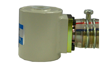
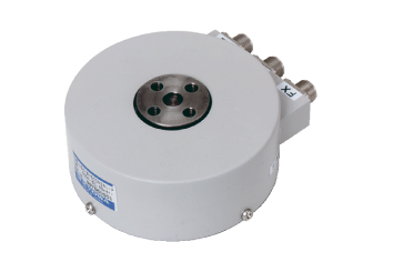
Parts Names and Principal Functions

(1)Mounting screw holes
Install the LFM-A using the screw holes provided on the top and bottom (P.C.D. 52 mm, 8-M4, depth 5) of the LFM-A.
(2)Positioning pin holes
Two pin holes (ø3H7) are provided at the same P.C.D. 52-mm positions as screw holes. Use these pin holes to align the centers of the equipment and the LFM-A. Pin holes are provided on the top and bottom of the LFM-A.
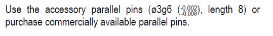
(Equivalent product) SKFA-GG3-P3.00-L3-B4.5-E0.5-A45 (MISUMI made)
(3)Loading direction
Determine the force detecting direction of the LFM-A by using the positioning pin holes as reference. Connect the 2 pin holes on one side of the LFM-A to provide the X-axis, and specify the fixing bracket side as the positive direction. Consequently, the side where cover set screws are located becomes the negative direction.

4. Installation
4.1 Prior to Installation Before installing the LFM-A, take note of the following points.
a. Precautions on overload
Do not apply load exceeding the safe overload on the LFM-A. Applying such an excessive load may cause damage to the LFM-A. If impact load is applied, a force several times larger than the applied load acts upon the LFM-A. Pay due attention and handle the LFM-A with special care during work.
b. Flatness of the mounting surface of the measuring target Since the LFM-A is installed on the measuring target by means of surface contact, uneven contact surface may affect the characteristics of the LFM-A. To prevent adverse effects on the LFM-A, it is recommended that the flatness of the mounting surface contacted with the LFM-A should be adjusted to 0.01mm or less with ø64 mm in outer diameter and ø42 mm in inner diameter.

c. Mounting accuracy
The LFM-A is designed to detect 6-component force based on the coordinates of 3 reference axes (X, Y and Z-axes). If the LFM-A is not installed by perfectly aligning its coordinates with the coordinates of the measuring target, measured values may have a margin of error. For example, misalignment of 1 degree around the Z-axis generates an interference of approx. 1.7% in component forces FX and FY. Therefore, the LFM-A must be accurately installed in position to ensure accurate measurement.
d. Material of the measuring target If the material of the measuring target on which the LFM-A is installed is different from the LFM-A, the difference between the linear expansion coefficient of the 2 may change the zero point. At this time, take care to keep the temperature at the time of installation as it is during the measurement.

4.2 Installation Method
When installing the LFM-A on the measuring target, use the positioning pin holes to determine the force detecting direction. Check the positional relation between the LFM-A force detecting direction and pin holes.
CAUTION
When machining the equipment, take special care for the strength of the equipment. If the machine processed equipment does not have sufficient strength, it may break and fall during use or cause unexpected accident.
CAUTION
If location of the mounting holes are misaligned or the bolts are not inserted vertically, the screw holes of the LFM-A may be damaged.
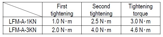
Tighten the bolts using a torque wrench, etc. The recommended tightening torque is 4.6 N・m for the LFM-A-3KN and 3.0 N・m for the LFM-A-1KN. Do not tighten the bolts with the specified torque in one go, but tighten them in diagonal pairs. Tighten one bolt, then tighten the bolt on the diagonally opposite side, and repeat this 3 times or so until both bolts are securely tightened.
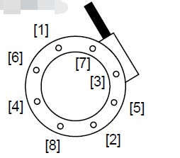
Tighten the bolts in diagonal pairs.
CAUTION
Be sure to observe the specified tightening torque. If the tightening torque is smaller than the specified torque, the measurement accuracy of the LFM-A may be decreased or the mounting screws may become loose during use. On the other hand, applying excessive tightening torque may damage the threads of the LFM-A and render it unusable.
5. Cable Connection
Connect the LFM-A cable to the measuring device.
| C H |
W ir e c o lor |
Sy m bo l |
C ir c u it |
| F1 |
O r ange |
- |
R e d |
Input (+ ) |
| G r a y |
- |
B lac k |
O utput ( - ) |
| O r ange |
- |
B lac k |
Input (- ) |
| G r a y |
- |
R e d |
O utput ( + ) |
| M 1 |
W h ite |
- |
R e d |
Input (+ ) |
| Ye llo w |
- |
B lac k |
O utput ( - ) |
| W h ite |
- |
B lac k |
Input (- ) |
| Ye llo w |
- |
R e d |
O utput ( + ) |
| F2 |
P ink |
- |
R e d |
Input (+ ) |
| O r ange |
-- |
B lac k |
O utput ( - ) |
| P ink |
- |
B lac k |
Input (- ) |
| O r ange |
-- |
R e d |
O utput ( + ) |
| M 2 |
G r a y |
-- |
R e d |
Input (+ ) |
| W h ite |
-- |
B lac k |
O utput ( - ) |
| G r a y |
-- |
B lac k |
Input (- ) |
| W h ite |
-- |
R e d |
O utput ( + ) |
| F3 |
Ye llo w |
-- |
R e d |
Input (+ ) |
| P ink |
-- |
B lac k |
O utput ( - ) |
| Ye llo w |
-- |
B lac k |
Input (- ) |
| P ink |
-- |
R e d |
O utput ( + ) |
| M 3 |
O r ange |
-- - |
R e d |
Input (+ ) |
| G r a y |
-- - |
B lac k |
O utput ( - ) |
| O r ange |
-- - |
B lac k |
Input (- ) |
| G r a y |
-- - |
R e d |
O utput ( + ) |
| F4 |
W h ite |
-- - |
R e d |
Input (+ ) |
| Ye llo w |
-- - |
B lac k |
O utput ( - ) |
| W h ite |
-- - |
B lac k |
Input (- ) |
| Ye llo w |
-- - |
R e d |
O utput ( + ) |
| M 4 |
P ink |
-- - |
R e d |
Input (+ ) |
| O r ange |
---- |
B lac k |
O utput ( - ) |
| P ink |
-- - |
B lac k |
Input (- ) |
| O r ange |
---- |
R e d |
O utput ( + ) |
6. Output/Conversion
The LFM-A outputs 8 strain components F1 to F4 and M1 to M4.
• Measuring ranges are set as follows:
F1 to F4: 5000 μm/m (or more)
M1 to M4: 10000 μm/m (or more)
Take measurement using a constant voltage measuring instrument within the recommended excitation voltage range. To obtain accurate and safe measurement, change the measuring ranges to appropriate levels while conducting the measurement. The measured outputs are converted into outputs of 6-component forces by the following equations:
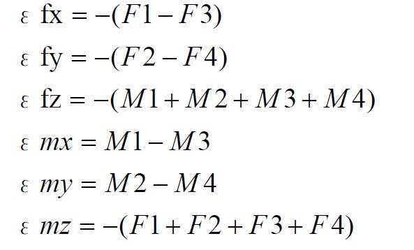
Next, interference correction is made. The calculated outputs of the 6-component forces are processed with a calibration constant matrix to obtain physical values of 6-component forces (loads FX, FY and FZ and moments MX, MY and MZ).
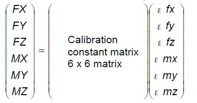
The accessory CD-ROM contains calibration constant matrix data as well as an Excel file for simplified output conversion designed to convert outputs from the LFM-A into loads/moments (This file is created using Microsoft Corporation’s Microsoft Excel).
7. Excel File for Simplified Output Conversion
This Excel file is used to calculate physical values from strain outputs of the LFM-A. By entering strain outputs of 8 components, physical values of 6-component forces can be obtained through calculations. See the following steps to use this file. (1)Input a calibration constant matrix. Input a calibration constant matrix in the “Calibration Constant Matrix” sheet. The calibration constant matrix of the LFM-A is written in the accessory CD-ROM in advance.

(2) Convert into physical values Enter the desired data (Unit: μm/m) of the LFM-A outputs you want to convert in the “Data Conversion Software” sheet and then, click the Execute of Conversion button.
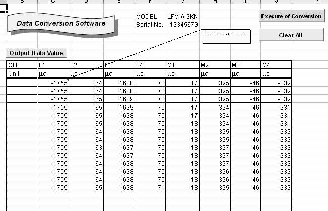
The converted physical values are displayed.
8. Precautions for Storage and Inspection
If the indicated value is unstable or abnormal, check the LFM-A is correctly and securely connected to the measuring device, and also check the LFM-A is used according to the specified
instructions. If no abnormality was found, check the following i tems on the LFM-A.
(1)Check bridge resistance with a tester, etc. The input resistance and output resistance should be in a range of 350 Ω ± 3%.
(2)Check insulation resistance between the LFM-A mainbody and any cable conductor wires except the shield wire with a tester, etc. Do not use a Megger for the measurement. The insulation resistance should be 100 MΩ or more (Measurement voltage: 50 V or less).
If any of the above measured value is abnormal, contact KYOWA or our representative.
9. Specifications
Rated Capacity, Rated Output, Natural Frequency
| Model |
Top: Rated capacity / Bottom: Rated output |
Natural frequency |
| FX, FY |
FZ |
MX, MY |
MZ |
| LFM-A-1KN |
1kN |
1kN |
50N・m |
25N・m |
Approx. 5kHz |
| 1.5 mV/V or more |
1.8 mV/V or more |
4.0 mV/V or more |
2.4 mV/V or more |
| LFM-A-3KN |
3kN |
3kN |
100N・m |
50N・m |
Approx. 5kHz |
| 1.6 mV/V or more |
1.6 mV/V or more |
2.4 mV/V or more |
1.6 mV/V or more |
Note) The above values are 6-component force outputs converted from 8-component outputs.
10. Load Directions and Outputs

11. Outside View


 售前咨询
售前咨询